

As a lengthy commissioning phase nears completion, and a new pope is about to be elected, it’s a timely coincidence that Carbon Clean is set to announce its arrival with plumes of white smoke. This pyrolysis facility has been years in the making. The following is a brief account of the design of this pyrolysis plant’s new cowl.
A cowl with a new form has been imagined, prototyped, iterated, drawn, and priced. It will be installed in a couple of weeks. It has been designed to solve a practical problem, but it is the only publicly visible element of the new pyrolysis plant within The Old Bacon Factory. The cowl is not just a technical element; it signals a new life for The Old Bacon Factory.
Why a Wind Assisted Cowl
During commissioning, the need for greater flue draught was identified. There were several options that could have been chosen for increasing the draught. We decided to stick with a quick-to-implement option: a wind-assisted cowl. As the cowl rotates, it creates a partial vacuum. The negative pressure induced by the cowl (relative to atmospheric pressure) pulls flue gases up and out of the stack at a faster rate compared to without it. With this improvement, and several others, the system’s seals will function better; therefore, higher throughputs of material can be processed while maintaining seal integrity and safe operating conditions. With draught enhancement decided, attention turned to rapid prototyping—trading CFD depth for speed of insight.
Design and Prototyping
Although this first iteration is a rapid prototype rather than a full CFD‑backed design, it nevertheless provides a solid proof‑of‑concept. Additionally, and more importantly, it provides a base for further refinement, testing, understanding, and system control in the future. Finally, it was much faster to design, iterate, and implement than other suitable but more complex and expensive options. We sketched, 3d modelled and 3d printed at various scales.
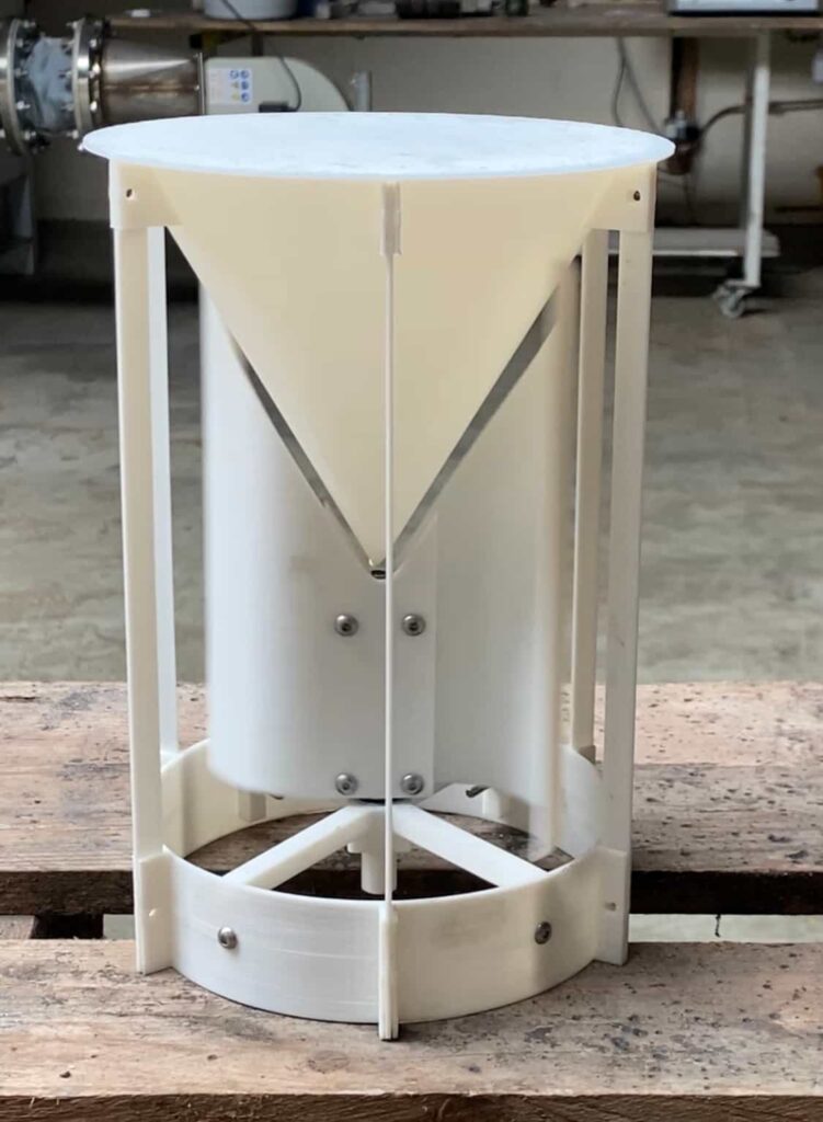
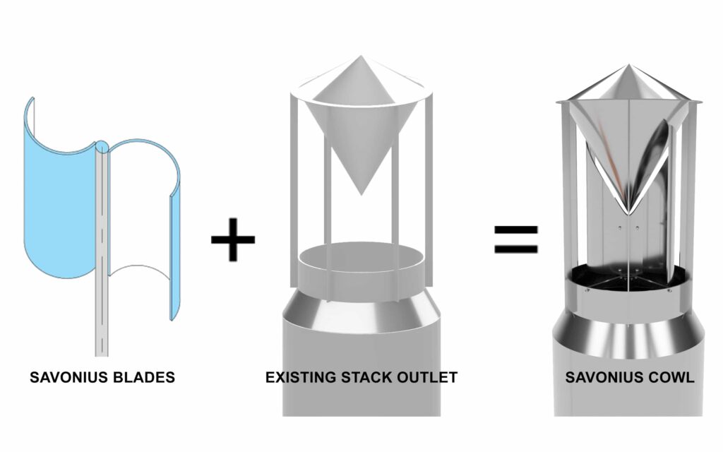
Its form is influenced by a couple of things. First, the stack outlet had already been installed with an inverted cone to assist with flue gas dispersion and to prevent rain ingress. Secondly, and leading on directly from the consequences of the first point, a traditional cowl could not be installed without removing the inverted cone. We decided the cone was to remain in place and to look for a different form of cowl.
After a brief but focused period of searching for a suitable form factor, a Savonius-type blade arrangement was chosen. It ticked a number of boxes:
- it could be made to fit into the existing stack outlet;
- Savonius rotors are self-starting at low wind speeds;
- they generate high torque even at relatively low speeds;
- and the rotors create the desired low-pressure zone by displacing air as they spin.
Having settled on the Savonius form, we then turned to published dimensional guidelines (Manavar 2023) to refine blade geometry.
Next Steps & Control Strategy
This wind-assisted cowl will provide proof of concept and fit. But how could this design be improved? With the prototype soon to be installed, we can already look ahead to how active control might sharpen performance. With many system parameters already set, like stack height, diameter, insulation levels, and other factors to consider including wind speed, ambient temperature, and variable process temperatures, the next area for improvement will be control of cowl rotational speed. If it works well, and we decide we want even more control, we will have the option to fit it with some sensors, a motor, and a VSD. Ultimately, we plan to integrate a future version of the cowl into our control system. By measuring live process conditions, we can begin to understand how internal, external, controllable, and uncontrollable factors interact—allowing us to optimise the cowl’s rotation speed to achieve ideal draught pressure under all operating conditions. This wind-assisted cowl is simply a first draft design.
Imaginitive Exploration

In this space between fabrication and installation, I wanted to visualise the interaction between the flue gas exiting the stack and our proposed new cowl. This isn’t a factually accurate, physics-based simulation but a speculative artistic impression. After the intense focus of researching and producing technical drawings for a functioning prototype, I wanted the space to dream again. How might the stack look to the public? What if the flue gas was sculpted as it exited to the atmosphere? How does it signal a brighter future to the world? Yes, this new clean technology does produce emissions. It’s not perfect, but we know, however, that it’s a cleaner, more desirable solution than the status quo for many thousands of tons of material that is currently shipped abroad or incinerated in Ireland. So, while we wait for fabrication and installation to complete and for a new pope to be elected, here are some artist’s impressions of how some white smoke could signal a brighter future: it’s not perfect, but it could be better than today.
Referenced research paper:
Manavar, Vatsalkumar Arvindbhai. 2021. Design Optimization of Savonius Wind Turbine using CFD Simulations. Master’s thesis, Faculty of Science and Technology, Uppsala University. Supervisor: Anders Goude; Subject reader: Hans Bernhoff; Examiner: Irina Temiz
Terminology: Cowl (savonius rotor assembly)
Visualisation tools: The renders and animation of the stack elements and gas were made using Blender. I wanted to play with the software to see what could be produced. I’m in awe of the power and versatility of Blender. What an amazing tool for visualisation and storytelling.